Jaguar 5-way BIOS Modification
Introduction
When modifying my Jaguar CD into a Developer
CD I found the need of having multiple BIOS versions in my Jaguar. The
Developer CD needs the Stubulator '94 BIOS but I also wanted to use the
BJL BIOS
of Bastian Schick. The solution: Look at the excellent description of the
BJL
installation by
Matthias Domin but use a bigger EPROM, program it with multiple BIOS versions and make the upper
address lines switchable.
I used a 512Kb EPROM so I can have 4 different BIOS versions. My Jaguar now
has Stubulator '93, Stubulator '94,
BJL 1.06 and
JagOS 1.03 and of course the original boot ROM.
Warnings
Adding a new BIOS chip to your Jaguar is not easy. To do this you need a lot
of soldering experience and a lot of patience. Do this modification at your own risk and don't blame me if something goes wrong.
Requirements
- A Jaguar of course.
- A 29F040 or compatible Flash ROM.
A 27C4001 EPROM is also possible but it needs different wiring. Besides that it is more expensive
and harder to erase. That's why using a 27C4001 is not further explained here.
- An EPROM programmer to program the 29F040 Flash ROM. (Or a friend,
friendly neighbor, colleague or electronics
shop with a programmer)
- The BIOS ROM images you want to use e.g.:
- A toggle switch.
- A 4 bit (16 positions) rotary switch with hexadecimal encoding. Currently
only 4 positions are used but in a later stage we could use a bigger EPROM to
switch between more BIOS versions.
If you can't find a rotary switch you can also use two toggle switches
instead.
- A 32 pin IC socket.
- Four 47K resistors. 4K7 resistors will also work.
- Conducting wire.
- A small solder iron.
- Philips screwdriver.
Simplified schematics
The modification works by soldering a Flash ROM with the new BIOS versions on
top of the original BIOS ROM. Most pins are soldered on the original ROM except
for pin 1, 22 and 30. A toggle switch is used to switch between the two ROM
chips. A 4-bit rotary switch is used to select the BIOS version in the Flash
ROM. The schematics below show the connections of the ROM chips that are not
connected directly on the PCB anymore.

Step-by-step guide
- First take your Jaguar apart and remove the shielding so you only have the
PCB. Locate the BIOS chip which is the big 32 pin chip at the upper right part
of the PCB (near the power connector).
- Cut pin 22 (/CE) as close to the PCB as possible. Bend pin 22 of the chip
up. Be careful not the break it.
- Get the IC socket. Bend pin 1 (A18), pin 22 (/CE) and pin 30 (A17) up to
the outside of the socket.
- Solder the IC socket on top of the ROM chip. Make all connections except
for pin 1, 22, and 30.
- Solder a 47K resistor between pin 22 (/CE) of the ROM chip and and pin 32
(VCC).
- Solder a 47K resistor between pin 22(/CE) of the IC socket and pin 32 (VCC).
- Solder three wires to the toggle switch. The common contact (The middle
one) goes to /CE on the PCB (there where you cut the pin 22 of the chip).
Easiest is to solder the wire at the bottom of the PCB.
The other two wires go to respectively pin 22 of the BIOS chip and pin 22 of
the IC socket.
With this switch we can now switch between the original BIOS chip and the new
BIOS chip.
- Solder a 47K resistor between pin 1 (A18) of the IC socket and pin 16
(ground).
- Solder a 47K resistor between pin 30 (A17) of the IC socket and pin 16
(ground).
- Solder three wires to the rotary switch. The common contact goes to pin 32
(VCC) of the BIOS chip. Bit 0 of the rotary switch goes to pin 30 (A17) of the
IC socket. Bit 1 of the rotary switch goes to pin 1 (A18) of the IC socket.
Bit 2 & 3 of the rotary switch remain unconnected.
Now we can use the rotary switch to select one of the 128Kb banks of the Flash
ROM chip.
- Find a nice place in the Jaguar's housing for the toggle switch and rotary
switch. I placed them at the upper right of the housing.
- Program the Flash ROM with the BIOS versions you want. Program in each
128Kb block a BIOS:
$00000 - $1FFFF: First BIOS
$20000 - $3FFFF: Second BIOS
$40000 - $5FFFF: Third BIOS
$60000 - $7FFFF: Fourth BIOS
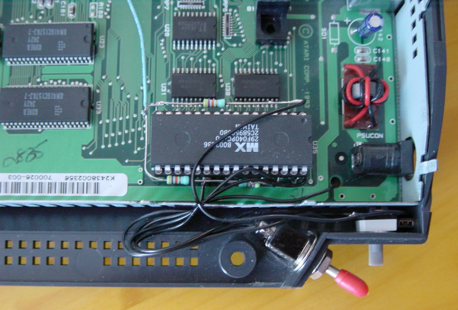
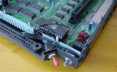
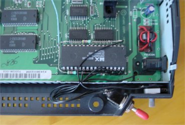
- Insert your freshly programmed Flash ROM in the IC socket. If everything
went well your Jaguar will look similar to this (Note: the blue wire in the
pictures is part of a
reset switch and not part of the BIOS upgrade):
Finally reassemble your Jaguar. The toggle switch will switch between the
original BIOS and an extra BIOS. The rotary switch determines which extra BIOS
to use.